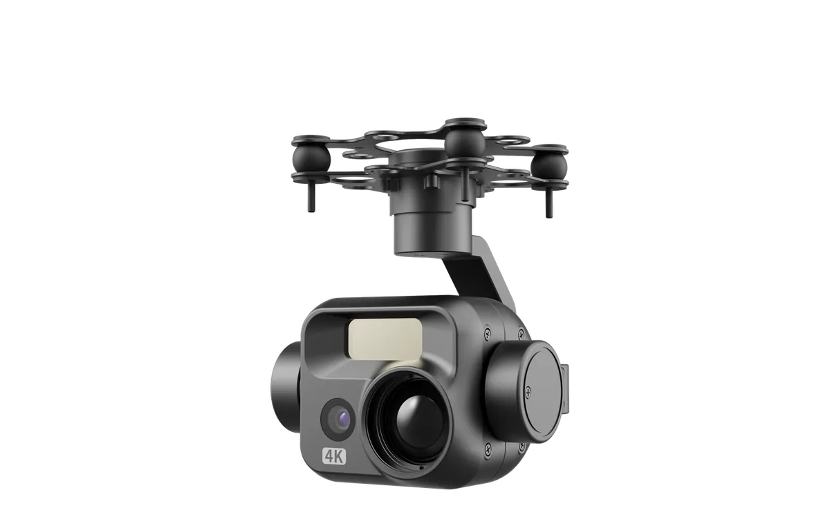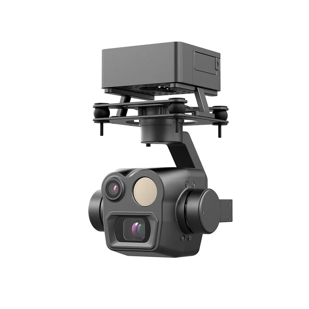
Last month an integrator working on power line inspection sent over a clip from the field. The aircraft was hovering roughly 700 m from the conductor. The conductor was clearly visible in the frame, and the crosshair was sitting right on it.
Then he pressed the ranging button. The screen returned a number: 312 m.
Not 700. Not 1300. 312. He thought the unit was faulty and asked me to look at the specs. Two glances were enough. By that distance the laser spot had grown several times wider than the conductor itself, so the beam was hitting the hillside behind it. 312 m was the hillside.
The case is typical. Most articles about laser rangefinders recite the same numbers: 905 nm, ±1 m, 1200 m range. But what actually breaks projects is never those numbers. It is three physical facts almost nobody publishes: the spot widens with distance, an oblique shot cuts the range dramatically, and small targets and large targets do not share the same usable range.
This article covers all three. What your gimbal is rated for, and what you can actually range, are usually not the same figure.
Updated October 2026. Specifications cited for our gimbals come from factory data sheets. References to industry practice and third-party figures are attributed in the text.
Start Here: A Laser Is Not a Line, It Is a Cone That Spreads
Most people picture a laser as a perfectly thin line that hits exactly where you point it. A real laser beam is a cone that widens continuously from the aperture, and how fast it spreads is given by the beam divergence, measured in milliradians (mrad).
One conversion table shows why that number matters:
| Divergence | Spot at 100 m | At 500 m | At 1200 m |
|---|---|---|---|
| 0.65 mrad (typical 1535 nm module) | ~6.5 cm | ~33 cm | ~78 cm |
| 2 mrad (common on compact 905 nm modules) | ~20 cm | ~100 cm | ~240 cm |
| 10 mrad (entry-level modules; see published 1.5 km LRF gimbal specs) | ~100 cm | ~500 cm | Beyond range |
That last row is not invented. At least one manufacturer lists "divergence angle 10 mrad" on a 1.5 km ranging gimbal product page, meaning the spot gains roughly one meter for every 100 m of distance. That specification works fine for ranging buildings inside 200 m. Expect it to range a conductor at 800 m and the spot is already 8 m across, so it lands on whatever is behind.
Our own gimbal datasheets do not list divergence separately. That figure has to come from the supplier's batch-level data sheet. [verify manually] One rule of thumb still applies: at the same rated range, a tighter spot can range thin targets, while a wider spot suits area targets.
This also explains why so many users report that buildings range accurately while wires do not. Nothing is broken. The relationship between target size and spot size has changed.
The Same Module Loses Two Thirds of Its Range When You Shoot at an Angle
This is the second point almost nobody spells out. Effective ranging distance depends directly on the angle at which the beam strikes the target surface.
The more oblique the incidence, the less energy returns to the receiver, and the shorter the usable range. This is not theoretical. Manufacturers publish it as two separate figures. One laser ranging module on the market specifies 1800 m at normal incidence (1 Hz) and 600 m at oblique incidence, a 1:5 slant ratio (1 Hz). Same module, same target. Only the angle changed, and the range fell to a third.
Another example is the way range gets quoted across the industry. A 3 km-class gimbal module lists 3000 m against a "NATO standard target, 2.3 x 2.3 m" and up to 4000 m against large building targets. The gap between those numbers is target size.
Conversely, some manufacturers publish ranges by surface type. One model is quoted at 2000 m over grass, 1900 m over woodland and 1700 m over a road. Same device, different ground material, 300 m of difference.
All three examples point to the same conclusion: the range figure on a product page is an upper bound under the most favourable target and the most favourable angle. It is not a guaranteed working figure.
What This Means for Selection
If your work involves area targets such as building facades, hillsides, dams or fire scenes, the return is strong and you will get close to the rated range.
If your work involves linear targets such as power conductors, guy wires or bridge cables, you must account for both angle and spot size. The conductor is in the air, so an aircraft viewing it from below and to the side is naturally at an oblique angle. On top of that, a conductor is only a few centimetres thick, so a slightly wide spot misses it entirely. For this class of task, budgeting at half the rated figure is the safer assumption.
For point targets such as a single person or one component on a piece of equipment, add target reflectivity to the list. Dark clothing, rubber and wet timber all absorb the return.
Why We Do Not Use 1535 nm: An Honest Note on Selection
There is a clear trend in the industry over the past two years: new high-end electro-optical gimbals are increasingly moving to 1535 nm erbium glass lasers instead of 905 nm.
The reason is not complicated. At 905 nm, near-infrared, the eye's lens focuses the beam onto the retina, so power is constrained and eye-safety compliance is demanding. At 1535 nm the beam is absorbed by the cornea and lens before it reaches the retina, so a higher power output can be used within the same safety class, which means longer range. Atmospheric penetration is also better, with less attenuation in fog and dust. One manufacturer's technical material states that at equal power, a 1535 nm system can reach three to five times the range of a 905 nm system.
So why are our four gimbals still 905 nm? To be direct about it:
- Cost and size. 1535 nm needs indium gallium arsenide detectors, which makes modules larger, more expensive and more power-hungry. Our gimbal heads sit between 165 g and 280 g, and that envelope has to hold a tri-sensor or quad-sensor package (visible, zoom, thermal and laser). 905 nm is what fits today.
- Eye-safety class has to be confirmed per batch. 905 nm does not automatically mean unsafe. What matters is whether the power and pulse design achieve Class 1. We will not make that call on the supplier's behalf. [verify manually] Ask for the laser safety classification certificate for the specific batch you are buying.
- Inside 1200 m, 905 nm is entirely sufficient. For most city patrol, plant perimeter and station work, the aircraft stays inside 300 m. At that distance the difference between 905 nm and 1535 nm is not something an operator can feel.
So let us be explicit: if you specifically need beyond 1.5 km and stable operation in haze or dust, 1535 nm is the better choice, and that is not the scenario our current product line covers. When that requirement comes up, we handle it through sourcing outside our catalogue. Send us the range, the weather conditions and the target type, and the domestic supply chain has mature 1535 nm modules to match.
[verify manually] This section references third-party published specifications and industry practice. It does not constitute a performance claim for our products.
Rated Range and Working Range Can Differ by More Than Half
Stack the factors above and the "usable range" of a gimbal becomes a band, not a fixed number. The same 1200 m module can behave very differently depending on conditions.
| Conditions | Target type | Usable range (relative to rating) | Note |
|---|---|---|---|
| Normal incidence, clear weather, area target | Building, hillside | Close to the rating | Best case; the rating is achievable |
| Normal incidence, clear, linear target | Conductor, guy wire | Roughly half to seven tenths of the rating | Limited by spot size, depends on pulse and aim |
| Oblique incidence (approx. 1:5 slant) | Any | As low as one third of the rating | Manufacturer-measured, not theoretical |
| Rain, fog, dust | Any | Clearly reduced | Return attenuated by atmospheric scattering |
| Dark or absorptive target | Wet soil, dark clothing | Reduced | Weak return signal |
| Multiple overlapping targets | Woodland, dense structures | Reduced | Pulse energy is split across returns |
Across this table, changing nothing but the angle can take the same device from close to its full rating down to one third of it.
A Measured Distance Still Has to Be Converted Before It Is Usable
Now the third layer. Even when the laser hits the target cleanly, what it returns is slant range, the straight-line distance from aircraft to target. Everything downstream, from dispatching a team to judging a boundary crossing to marking a point on a map, uses horizontal ground distance.
The two are equal only when the aircraft and the target are at exactly the same height. In practice that condition rarely holds.
How Large Is the Difference
The formula is simple: ground distance = slant range x cos(pitch angle). But how much it matters is where most people lose track:
| Target ground distance | Flight altitude | Laser reading (slant) | Error if used as ground distance |
|---|---|---|---|
| 600 m | 120 m | ~612 m | +12 m |
| 600 m | 300 m | ~671 m | +71 m |
| 600 m | 500 m | ~781 m | +181 m |
| 1200 m | 300 m | ~1237 m | +37 m |
Look at the second and third rows. At the same 600 m ground distance, flying at 300 m produces a 71 m error, while flying at 500 m produces 181 m. The error grows with altitude, not with distance. The higher you fly, the more slant range diverges from ground distance, which runs against most people's intuition.
That leads to a counter-intuitive practice note: if you need an accurate horizontal distance to a target, favour flying lower. When the aircraft sits near the target's own height, slant range and ground distance converge. Real missions still have to balance safe altitude and field of view, but the trade-off is worth stating plainly.
Angular Error Gets Amplified by Distance
The second piece of arithmetic is less obvious. The laser's own accuracy is ±1 m, but the final position accuracy adds angular error on top:
| Target distance | Angular error 0.5° | 1° | 2° |
|---|---|---|---|
| 300 m | ~2.6 m | ~5.2 m | ~10.5 m |
| 700 m | ~6.1 m | ~12.2 m | ~24.4 m |
| 1200 m | ~10.5 m | ~20.9 m | ~41.9 m |
The industry puts this directly into specifications. One manufacturer quotes target designation accuracy of "1 km at 20 m", meaning roughly 20 m of position error when marking a point at 1 km. The same device's laser ranging accuracy is specified as ±(0.2 m + D x 0.15%), which at 1 km works out to about ±1.7 m.
1.7 m against 20 m, a factor of ten. What accounts for that factor is attitude and angular resolution. No amount of laser precision compensates for attitude data between the gimbal and the flight controller that is not accurate enough, and the marked point will still drift.
[verify manually] The geometric conversion tables above are simplified horizontal-projection calculations. They do not include gimbal mounting offset or flight controller attitude solution error. Actual position accuracy must be measured on the specific platform.
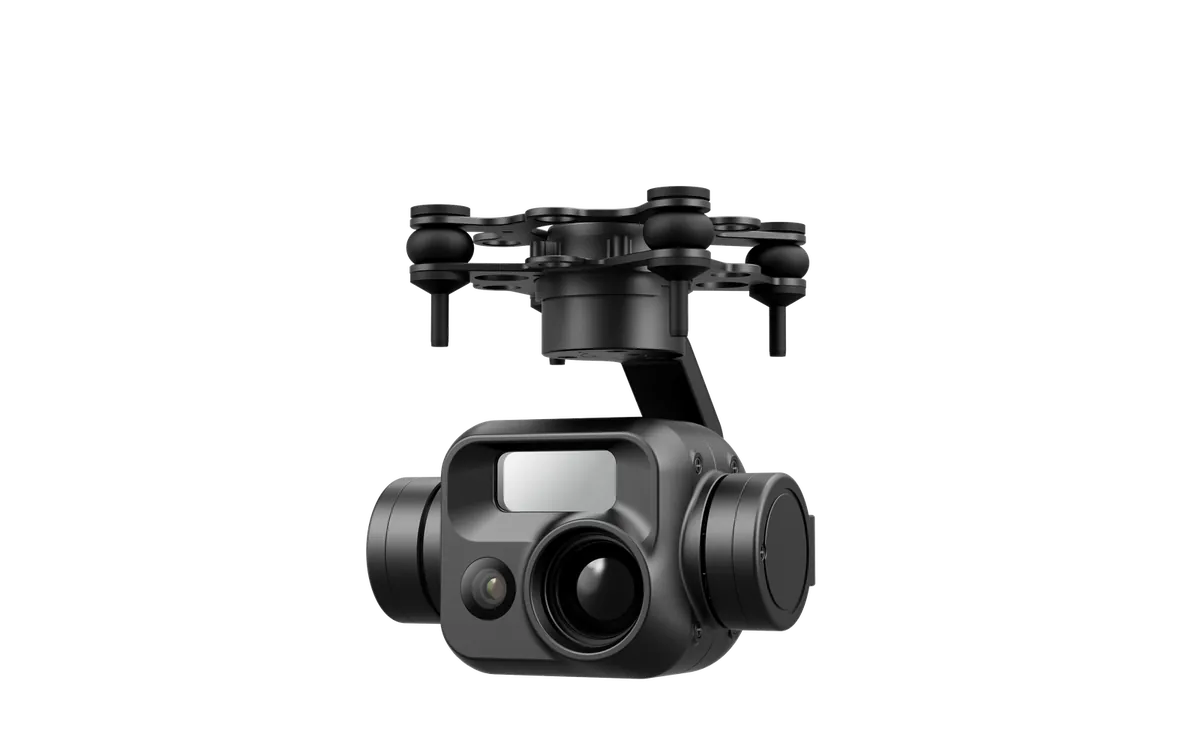
Choosing Between Our Four Gimbals
Following the logic above, selection should start from the mission, not from the maximum range figure.
| Model | Laser rangefinder | Continuous ranging | Day / night recognition | Gimbal weight | Suited to |
|---|---|---|---|---|---|
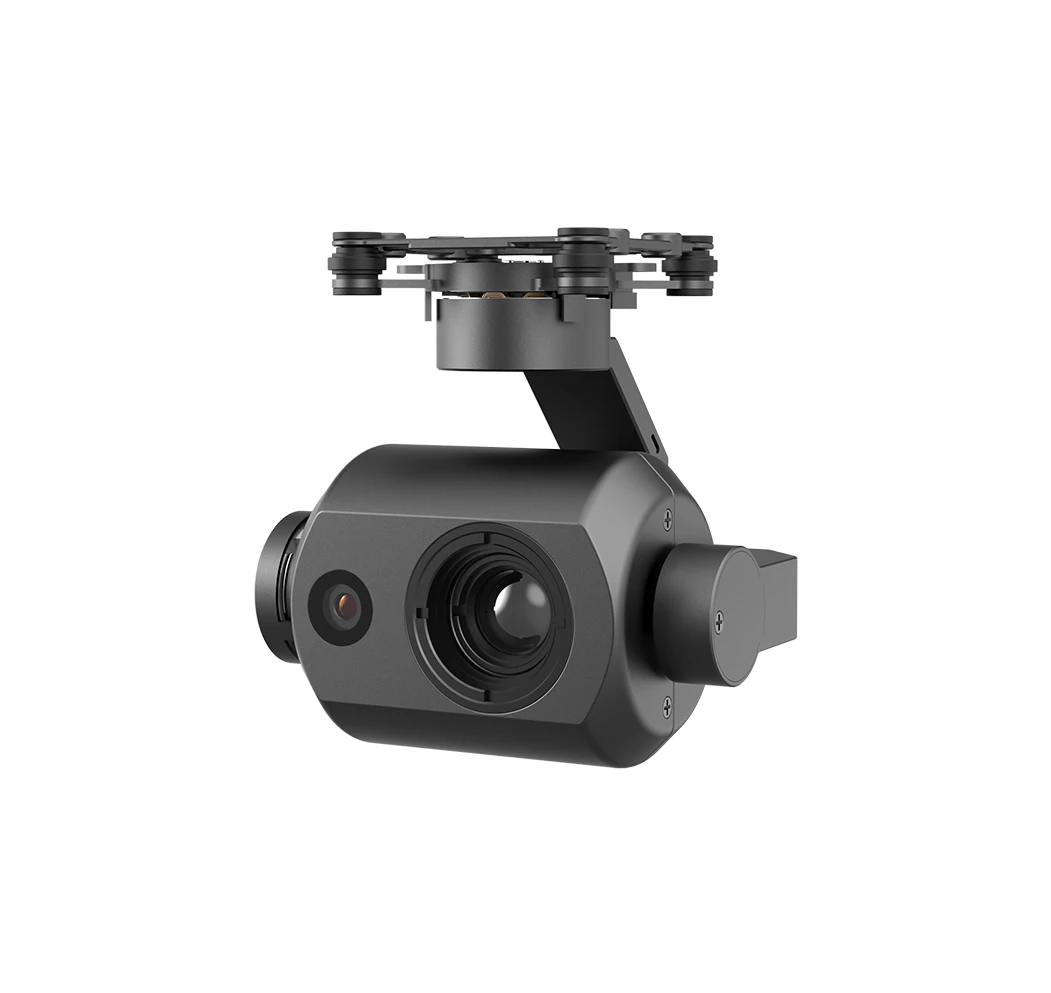
| PUTT225 | 905 nm, 10–700 m, ±1 m | Not listed on the data sheet [verify manually] | >1500 m / not listed | 225±5 g | City, plant, station interiors; short and mid-range point marking |
| PUTF270 | 905 nm, 10–1200 m, ±1 m | Not listed on the data sheet [verify manually] | >1500 m / >300 m | 280±5 g | Long-range point marking; quad-sensor wide + zoom + thermal + laser |
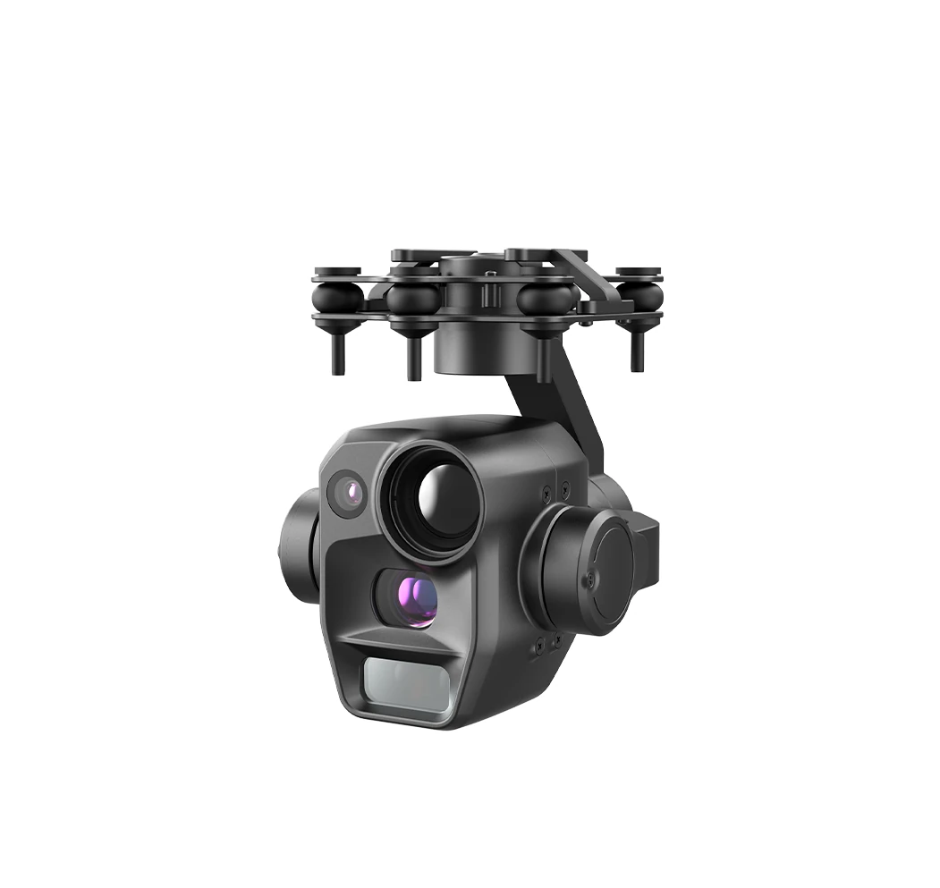
| PUTT170 | 905 nm, 10–1200 m, ±1 m, ≤4 Hz | ≤4 Hz | >400 m / >300 m | 175±5 g | Long-range continuous ranging; can follow moving targets |
| PUTT155 | 905 nm, 10–1200 m, ±1 m, ≤4 Hz | ≤4 Hz | >400 m / >220 m | 165±5 g | As above, the lightest of the four |
One detail is easy to miss: the PUTT225 is rated above 1500 m for daytime recognition, but its laser only reaches 700 m. Those two figures are often read together, as if the whole chain reached 1500 m. In practice the zoom can see it while the laser cannot measure it. Recognition distance and ranging range are entirely separate specifications.
As for the 500 m between the 700 m and 1200 m classes, it is not a question of a bigger number. It is the boundary between mission types:
- City patrol, plant perimeter, station interior: the aircraft normally works inside 300 m, so 700 m leaves ample margin. Choose the PUTT225.
- Long-haul oil and gas pipelines, transmission corridors, open terrain: working radius routinely exceeds 1 km, and 700 m becomes the bottleneck. Move to the 1200 m class.
- Moving targets (vehicles, people, vessels): beyond range, confirm continuous ranging capability. The models currently specified at ≤4 Hz are the PUTT155 and PUTT170.
Get the order right: define the maximum ranging requirement from the mission first, then choose the laser class, and only then compare zoom ratios. Doing it in reverse is how buyers end up with an impressive zoom paired with a laser that cannot reach.
What ≤4 Hz Decides: Whether It Can Follow a Vehicle
Continuous ranging frequency is a parameter that sales language tends to obscure. 4 Hz means at most four distance readings per second. Whether that is enough can be worked out directly:
- Walking target (about 1.5 m/s): the target moves less than 0.4 m between readings. Plenty dense for a track.
- Vehicle target (about 15 m/s): the target moves some 3.8 m between readings. Enough to show the general direction, not enough for fine manoeuvre.
- High-speed target (above 30 m/s): more than 7.5 m between readings. Good only for a rough heading, not for precise tracking.
One point is easily confused here: 4 Hz is the ranging frequency ceiling, not the output rate of the whole tracking system. The frame rate of an AI tracking module is a separate specification. The usable update rate is whichever of the two is lower.
Single-shot and continuous ranging are two modes of use, and the difference is in the control logic, not the hardware. A model that does not list a frequency is not necessarily incapable of continuous ranging, but an unconfirmed capability should not be treated as a default when building a proposal.
Five Mistakes That Come Up Most Often With Laser Rangefinders
Listed by how frequently they occur. The first is the most common.
Mistake 1: Treating the Rated Range as a Guaranteed Figure in a Proposal
The 1200 m on the product page is an upper bound under ideal conditions. Oblique incidence, a small target or bad weather, any one of them discounts it. In the conditions table above, the same device drops from close to full rating down to a third, purely on angle.
Fix: quote a band rather than a single number when writing proposals. Area targets can be quoted near the rating, linear targets at about half, and adverse weather separately.
Mistake 2: Assuming Building Experience Transfers to Wires
A building is a surface, a conductor is a line. At the same distance, the return from the former is orders of magnitude stronger. That is exactly what produced the opening case: a spot larger than the target, landing on the background.
Fix: for projects involving thin or linear targets, confirm the divergence figure first and then verify by measurement. Do not infer "wires range well" from "buildings range well".
Mistake 3: Reporting Slant Range as Ground Distance
At 300 m altitude and 600 m ground distance, the error is 71 m. Raise it to 500 m altitude and the error is 181 m. In dense suburban or plant environments, a hundred metres is enough to point at the wrong building.
Fix: confirm the system applies a pitch-angle conversion. If it does not, descend to near the target's height before ranging, so the two figures converge.
Mistake 4: Assuming a Laser Alone Produces Coordinates
Target designation = laser ranging + gimbal angles + aircraft attitude. All three are required. The gimbal can read a distance, but if attitude data does not flow through, the computed point still drifts. The industry figure of 20 m position accuracy at 1 km is what those three produce together, not what a laser achieves alone.
Fix: before purchasing, ask how attitude data travels between the gimbal and the flight controller. That answer determines whether point marking is usable more than the ranging specification does.
Mistake 5: Overlooking Target Reflectivity and Weather
A laser works on return signal. Dark, moisture-absorbing targets return weakly. Rain, fog and dust scatter and attenuate. One manufacturer publishes ranges separately for grass, woodland and road, with 300 m between them.
Fix: on the first flight of a new mission, range a few reference objects at known distances to confirm the achievable range, then plan the route.
The Short Version
A laser rangefinder's rated range is a ceiling, not a guarantee. A widening spot makes thin targets unrangeable, oblique incidence cuts range to a third, high flight pushes slant range away from ground distance, and attitude error turns ±1 m into a 20 m class position error. Select backwards from the mission: for city and plant work inside 300 m, the PUTT225 with its 700 m laser is sufficient; beyond 1 km in open terrain, move to the 1200 m class in the PUTT155, PUTT170 or PUTF270; if targets move, confirm continuous ranging, which the specifications list as ≤4 Hz on the PUTT155 and PUTT170. How far a zoom can see is a separate subject, covered in zoom versus fixed-focus gimbals; the weight a gimbal takes out of an aircraft's endurance budget is covered in how to allocate a micro gimbal SWaP budget.
Tell Us About Your Mission
Whether the rated range works for you can only be settled against your actual target. Send us the mission: how far you need to range, whether the target is a building, a line or a person, roughly what angle, and what weather and terrain. We will stack those factors together and tell you whether the 700 m class is enough or whether you need the 1200 m class.
- Integrators (power, emergency response, border projects): tell us the target type and working radius. We will estimate usable range separately for area, linear and point targets, and check whether your platform's attitude data path is complete.
- Distributors (when your customer is unsure about range): send the customer's operating conditions and we will advise on range and weight, with a sample configuration list.
- Longer range or 1535 nm wavelength: handled through sourcing outside our catalogue. Give us the range, weather conditions and target type, and the domestic supply chain will match a model.
How to reach us: leave a message on our inquiry page mentioning "gimbal laser rangefinder selection" and the technical team replies within 24 hours. Selection advice is free of charge.
FAQ: Frequently Asked Questions
My gimbal is rated 1200 m, so why can it not range a power line at 800 m?
Two causes combine. First, the laser spot widens with distance, and a typical 905 nm module can be over a metre across at 800 m, far wider than a conductor, so the beam lands on the background behind it. Second, a conductor is in the air and the aircraft views it from below and to the side, which is oblique incidence and significantly reduces return energy. One manufacturer's published specification shows the same module at 1800 m normal incidence and 600 m oblique.
Should I choose 905 nm or 1535 nm?
It depends on the mission. 905 nm is low cost, small and power-efficient, suited to work inside 1200 m with controllable weather. 1535 nm reaches Class 1 eye safety more easily, penetrates the atmosphere better, and at equal power can achieve three to five times the range of 905 nm, suiting work beyond 1.5 km or in haze and dust, at the cost of a larger and more expensive module. Our four gimbals use 905 nm, which is a choice driven by weight and cost constraints rather than an optimum for every scenario.
How much difference does normal versus oblique incidence make?
A large one. Take a module with published specifications of 1800 m at normal incidence (1 Hz) and 600 m at oblique incidence with a 1:5 slant ratio (1 Hz). That is a drop to a third. It is also why the usable range on linear inspection tasks is often well below the rated figure.
Why is position error at long range ten times the laser accuracy?
Because position accuracy is the sum of three parts: laser ranging accuracy, gimbal angular accuracy and aircraft attitude accuracy. The laser contributes ±1 m, but angular error is amplified by distance, where a 1 degree deviation produces about 21 m of displacement at 1200 m. The industry figure of 20 m position accuracy at 1 km is that combined result.
Does flying higher make ranging less accurate?
It widens the gap between slant range and ground distance. At the same 600 m ground distance, a laser reads about 612 m from 120 m altitude, about 671 m from 300 m and about 781 m from 500 m. So when you need an accurate horizontal distance, favour a lower flight altitude.
Is ≤4 Hz continuous ranging enough to follow a vehicle?
It depends on speed. At four readings per second, a walking target moves less than 0.4 m between readings, which is fine. A vehicle at 15 m/s moves about 3.8 m between readings, enough for direction but not fine manoeuvre. Above 30 m/s it becomes a rough heading only. Also note that 4 Hz is the ranging frequency; the frame rate of AI tracking is a separate specification, and the usable update rate is the lower of the two.
Which of the four gimbals support continuous ranging?
The models that explicitly specify ≤4 Hz are the PUTT155 and PUTT170. The data sheets for the PUTT225 and PUTF270 do not list a ranging frequency. That figure needs to be confirmed against the supplier's batch-level data sheet, and we will not draw that conclusion on the supplier's behalf.
Does weather affect laser ranging?
Yes, and substantially. Rain, fog and dust scatter and attenuate the laser energy, and dark or moisture-absorbing targets return weakly. One manufacturer publishes ranges by material, with the same device reaching 2000 m over grass, 1900 m over woodland and 1700 m over road. A rated figure is an ideal-condition value, so confirm it by measurement before the mission.
Which platforms can these four gimbals be fitted to?
A gimbal provides payload capability, and actual installation and compatibility must be assessed per platform, covering mounting points, power supply, weight margin and attitude data interface. The four gimbal heads range from 165±5 g to 280±5 g, with total weights between 207 g and 322 g, placing them in the micro-gimbal class. We do not commit to a compatibility range in advance; it has to be confirmed against the specific platform.
Disclaimer: Specifications for our gimbals are taken from factory data sheets. Third-party product specifications cited in this article (normal and oblique incidence range, beam divergence, range by material, target designation accuracy and similar) come from the relevant manufacturers' public product pages and technical material. They are used to illustrate general industry principles and do not constitute a performance claim for our products; our products have no compatibility or affiliation relationship with those manufacturers. The slant range conversion and angular error tables are example calculations derived from geometry, excluding gimbal mounting offset and flight controller attitude solution error. Actual position accuracy and effective ranging range must be confirmed by measurement on the specific platform and are subject to the supplier's latest data sheet.