Start with one number: 0.1 degrees.
If a gimbal's boresight is off by 0.1 degrees, then at 5 km the coordinates you report will be off by nearly 9 metres. How small is 0.1 degrees? Hold your arm out straight, and the thickness of your fingernail is about that angle. When you are searching a mountain at night for one person, what 9 metres means on the ground is something anyone who has been on that call already knows.
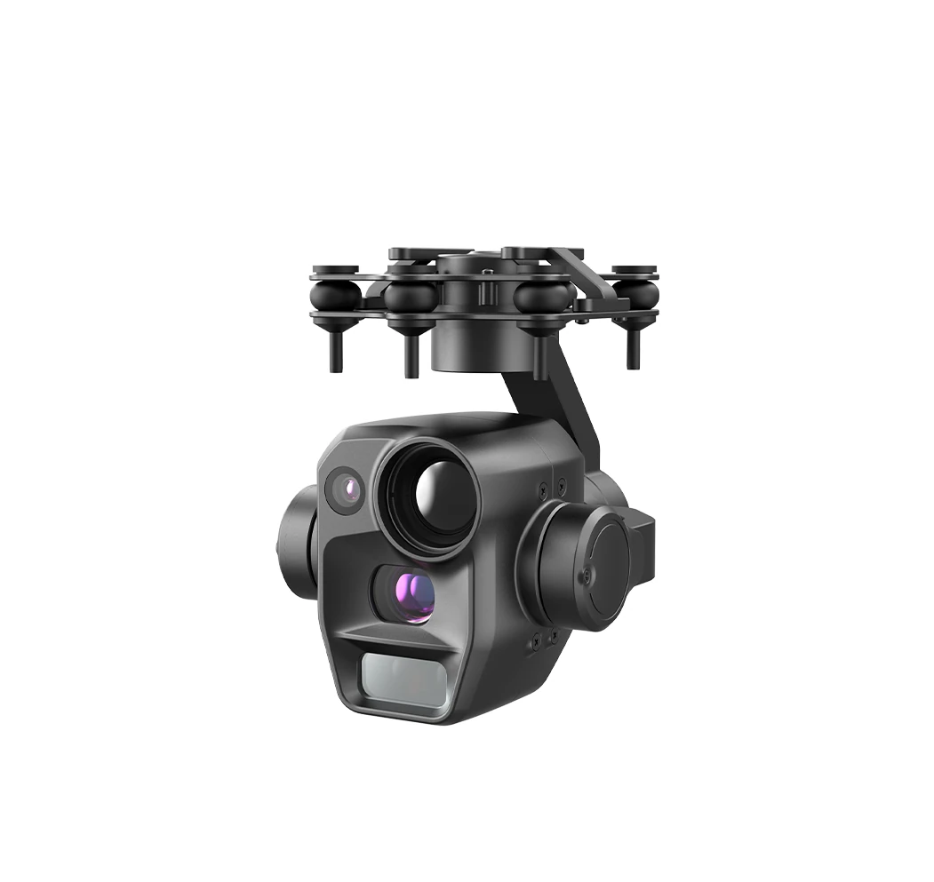
Most people imagine gimbal geolocation works like this: fire the laser once, the distance pops up, and the coordinates come with it. In the field it is nothing like that. Going from "the target is boxed on screen" to "here is a latitude and longitude" means tying together three sets of numbers — where the aircraft is, where the gimbal is pointing, and how far the target is. Two of those three do not live in the gimbal. That is why the same gimbal on a different aircraft can produce coordinates of a completely different quality.
This article covers three things: how the coordinates are actually computed, why we rate our accuracy as CEP 10 m, and why tracking a moving target is harder than watching a tree. By the end you should be able to answer one question — when a customer asks "can it report coordinates", does the kit you are holding actually deliver that.
Updated October 2026. The parameters in this article are factory specifications of our modules. Where we refer to industry practice or third-party data, the source is noted.
What You Report Is Not a Distance, It Is a Coordinate — and Three Things Stand in Between
A laser rangefinder gives you one number: how far the target is from the lens. But "how far" is not a coordinate. To turn it into a point on a map, the system has to know three things at the same time.
The first is where the aircraft is and which way it faces, from GPS plus inertial navigation and a compass. The second is how much the gimbal has turned relative to the aircraft, read in real time from the gimbal's own encoders. The third is how far the target is, from the laser. Combine the three and you can draw a ray from the aircraft; wherever the far end of that ray lands is the target's latitude and longitude. Remove any one of them and there is no coordinate. Of the three, only the third is measured by the gimbal.
If the Aircraft Does Not Know Where It Is, the Coordinate Is Wrong
This one is the most obvious and the most often skipped: the aircraft's position error passes straight through to the target. If the aircraft GPS is off by 5 m, the target coordinate is off by 5 m; off by 10 m, off by 10 m. One to one, with no attenuation.
There is no such thing as "a good enough gimbal rescuing the error" here — if the start of the ray is already wrong, a precise far end means nothing. So for missions that genuinely need accurate coordinates, the effort usually goes not into a better gimbal but into making the aircraft's positioning RTK-grade.
If the Gimbal Does Not Know Where It Points, the Error Grows With Distance
The second item is subtler. Boresight zero offset is a fixed small angle, but the displacement it causes scales linearly with distance: cross-range offset is roughly "distance × angular error". Work it through and it is clear:
| Target distance | Boresight off 0.1° | Boresight off 0.5° | Boresight off 1° |
|---|---|---|---|
| 500 m | about 0.9 m | about 4.4 m | about 8.7 m |
| 1 km | about 1.7 m | about 8.7 m | about 17.5 m |
| 2 km | about 3.5 m | about 17.5 m | about 34.9 m |
| 5 km | about 8.7 m | about 43.6 m | about 87.3 m |
Look at the last row. The same 0.1 degrees is 8.7 m at 5 km. What makes this painful is that on screen you cannot see that 0.1 degrees at all — the target box still sits dead centre. That is the real trouble with target geolocation: when it is wrong, nothing on the display tells you.
Boresight zero also drifts. After transport, a knock, or long hours of vibration, that zero quietly moves. So calibration is not a one-time job at installation; it belongs in the maintenance routine. Calibration drift is covered in Micro Gimbal SWaP Budget, and we will not repeat it here.
Why We Rate Accuracy as CEP 10 m Instead of "±10 m"
Customers reading the spec sheet often ask: a phone locates itself to a few metres, so why is your gimbal only 10 m? These two kinds of "positioning" are not the same thing at all. A phone measures where the phone is, straight from satellites. A gimbal has to work out where an object in the frame is, with an aircraft in flight, a gimbal rotating, and a laser beam that has to travel out and come back as a reflection in between.
We write the accuracy as CEP 10 m, and it is not an arbitrary round number. CEP is circular error probable: it means roughly half of the results land inside a circle of that radius, and half outside it. It describes a distribution, not a ceiling. Writing "±10 m" would read as "every point is within 10 m", which is a different claim entirely — and turning a fifty-fifty figure into a guaranteed one is exactly where the argument starts at acceptance testing.
So who contributes those 10 metres? Break it down:
| Error source | How it enters | Can it be reduced |
|---|---|---|
| Aircraft position | Passes to the target one to one | Yes — RTK is the most direct fix |
| Gimbal boresight calibration | Amplified by distance (see table above) | Yes — factory calibration plus periodic re-calibration |
| Laser slant range | Grows with distance, weather and target reflectivity | Partly — a better module, or shorter operating range |
| Target height assumption | Wrong assumption shifts the whole solution | Yes — measure with the laser instead of estimating |
Once you lay the four out side by side, it is clear that the share of those 10 metres that belongs to the gimbal itself is actually small — the bulk comes from aircraft positioning and boresight calibration. So if you want better coordinates, look at the aircraft first. This is also why we keep asking "what platform is this, and does it have RTK" during selection. That answer matters more to the final result than the gimbal model does.
One note on industry habit. The laser itself can reach ±1 m ranging accuracy, yet the position finally reported is often in the tens of metres. The missing factor of ten is eaten by attitude and angle solving. So when you see "laser accuracy ±1 m", do not read it as "position accuracy 1 m" — there are several layers in between.
Why Tracking a Moving Target Is Harder Than Watching a Tree
The words that show up most often in customer requirements are "track a person" and "track a vehicle". A fixed target is computed once and done. A moving target has to be computed continuously while it keeps moving, and the difficulty gathers in three places.
The Target Moves, So the Gimbal Has to Keep Up
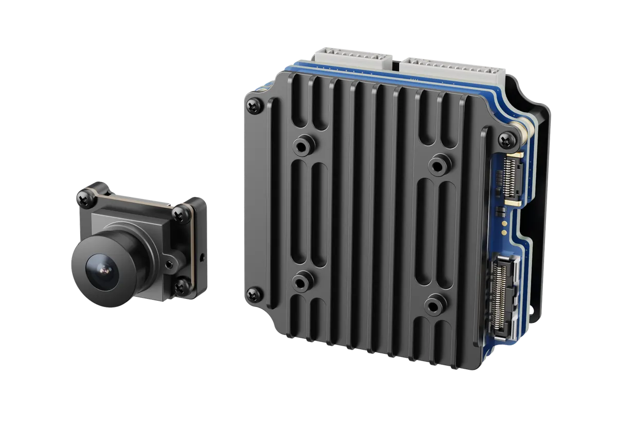
How fast a target moves across the frame depends on how fast it is really going and how far away you are. Close in and fast, it can jump a long way between frames, and an algorithm that hesitates loses it. That is why the wide-angle end needs a high frame rate — the short-focal channel on our PUDD075CW and PUDD075CCT runs 1280×720 @ 100fps precisely so a fast lateral mover does not slip between two frames.
After It Is Blocked, Can It Be Reacquired
In the real world a target disappears behind a tree, a wall, a bridge. The algorithm uses a motion model to estimate where it will reappear and reacquires the moment the occlusion clears; a weaker algorithm drops the track and an operator has to box it again by hand. Nobody can promise 100% reacquisition, but over one long mission the difference between "lost repeatedly" and "held throughout" becomes very large.
Switching to the Thermal Channel at Night Is a Different Job
Once it is dark, visible light is largely useless and the working channel is thermal. In the thermal channel a person is a bright blob on the frame, and tracking it feels nothing like chasing a coloured target in daylight — when the temperature contrast is low and the background is busy, the blob smears into the background. That is the reason dual-sensor and tri-sensor modules exist: visible light for detail by day, thermal to keep continuity at night.
Five Tracking Modules, Parameters on the Table
One thing to make clear first: all five are rated CEP 10 m for target geolocation. The difference is not "how accurately it reports" but "how long it can keep seeing, and how clearly". Everything below is factory calibration data.
| Model | Visible | Thermal | Recognition range (adult) | Weight | Steady-state power |
|---|---|---|---|---|---|
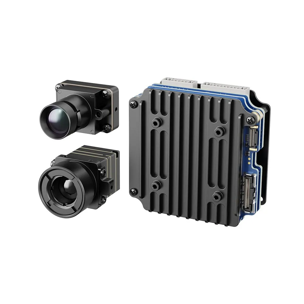
| PUDD075CW | 1.75 mm wide angle, 1280×720 @100fps | None | Daytime >80 m | Camera 10 g + AI module 42 g | ≤3 W |
| PUDD075CLT | 16.26 mm, 1080p @50fps | 384×288, 10 mm | Day >600 m; night urban low light >100 m | 35 g + 56 g | ≤5 W |
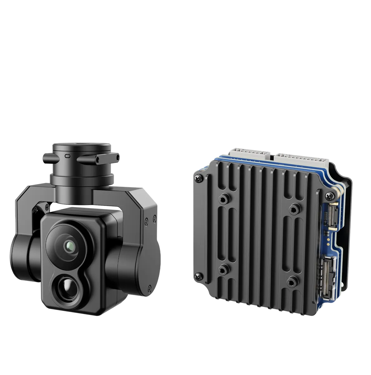
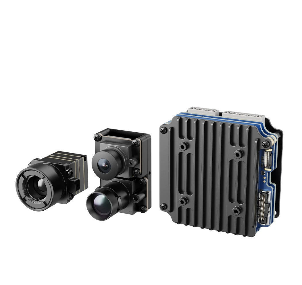
| PUDD075CCT | 16.26 mm tele + 1.75 mm wide | 384×288, 10 mm | Tele day >600 m / wide >80 m; night >100 m | 43 g + 56 g | ≤7 W |
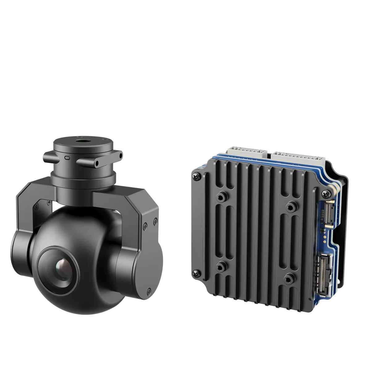
| PUDD075S | 8 / 12 / 16 / 25 mm options | None | Night >170 / 250 / 330 / 500 m (by focal length) | Gimbal 70 g + AI module 56 g | ≤10 W |
| PUDD075GT1/2/3 | 48 MP, 4.7 mm, 8K photo / 4K video | GT1 256×192@7 mm; GT2 384×[email protected] mm; GT3 640×[email protected] mm | Day >400 m; night >400–500 m | Gimbal 75–95 g + AI module 56 g | ≤9 W |
Spec sheets mix the words detection, recognition, tracking and positioning, and they do not answer the same question at all. Reading them interchangeably is the most common source of accidents:
| Term | What it answers | Rough criterion |
|---|---|---|
| Detection range | Is there anything in the frame | The target covers only two or three pixels — enough to see a shape |
| Recognition range | Person or vehicle — can it be classified | By Johnson's criteria, the target covers about 12 pixels |
| Tracking capability | Once locked, can it stay locked | Depends on contrast, target motion and gimbal servo |
| Position accuracy | Is the reported coordinate right | CEP 10 m across the range |
One counter-intuitive point has to be stated plainly: seeing clearly is not the same as computing accurately. You may clearly recognise a person at one kilometre and still report a coordinate twenty metres off. Image quality and coordinate accuracy are two separate chains, and mixing the two numbers in a proposal is the surest way to end up arguing at acceptance.
Review: The Five Places Target Geolocation Most Often Goes Wrong
Pitfall 1: Assuming "It Tracks" Means "It Reports Coordinates"
Tracking and geolocation are two separate chains inside the system, and some devices only track. When a customer says "we need coordinates", first confirm whether the kit actually outputs latitude and longitude. Do not take a tracking parameter and use it to answer a positioning requirement.
The fix: ask one question during requirements — "do you want it boxed on screen, or marked on a map". That one question saves most of the arguing later.
Pitfall 2: Reporting Slant Range as Ground Distance
The laser measures the straight-line distance from the lens to the target. With a steep depression angle, slant range and ground distance diverge badly: at 30° depression and 1,000 m slant, the ground distance is only about 866 m — a 134 m gap. In a suburb or an industrial site, a hundred-odd metres is enough to point at the wrong building.
The fix: before reporting, confirm the system applies a pitch-angle conversion. If it does not, bringing the aircraft down closer to the target's height is better than nothing, since the two numbers then nearly coincide.
Pitfall 3: Writing Guaranteed Figures From Ideal-Weather Accuracy
Spec-sheet accuracy is quoted under calibration conditions — visibility, humidity and target reflectivity all ideal. In dust, rain or fog, or with a target that sits at the background temperature, real results degrade. Put the nominal figure into a contract as a guarantee and it will not match at delivery.
The fix: read the nominal value as a ceiling and leave margin in the proposal. Never write CEP 10 m as "every point guaranteed within 10 m".
Pitfall 4: Ignoring That Boresight Calibration Drifts
This is the hardest one to self-check. When the calibration drifts, nothing shows on screen — the target box is still centred, and the coordinate has already moved. Only checking against a target of known coordinates will reveal it.
The fix: put re-calibration into the maintenance routine, and check it specifically after transport, a knock, or a payload swap.
Pitfall 5: Guessing the Target Height
Without live laser ranging, target height can only be assumed, and nobody tends to own that assumption. Whether the target stands on flat ground or on a rooftop can shift the landing point by hundreds of metres.
The fix: measure with the laser whenever you can; when it has to be an estimate, tell the customer it is an estimate and do not hand it over as a measurement.
In One Sentence
Tracking pins the target to the frame; geolocation pins it to the map, and between them runs the chain of aircraft attitude, gimbal angle and laser slant range. Break CEP 10 m apart and most of what decides success is not in the gimbal — it is in aircraft positioning and boresight calibration. So when a customer asks "can it report coordinates", the right question is not "which gimbal is most accurate" but "is my aircraft's positioning and attitude data chain sound". The mechanics of tracking itself are covered in AI Tracking Modules, and the traps around ranging in Gimbal Laser Ranging.
We Need Your Scenario
Target geolocation cannot be settled by parameters — it has to be measured against your mission. Send us the mission: what you need to track, roughly how far, what platform the aircraft is, whether it has RTK, and who uses the coordinates — we will stack those up and tell you whether this configuration can reach the position accuracy you need.
- System integrators (border, emergency response, power projects) → tell us the target type and operating radius; we work back from the required position accuracy to what the aircraft positioning and gimbal calibration must deliver
- Distributors (when the end customer is unsure) → send us the working conditions and we confirm module selection plus platform fit
- Needing longer range or higher accuracy → this goes through "sourcing beyond the catalogue"; write down the accuracy requirement and working conditions and our domestic supply chain will match a model
How to reply: leave a message on the site's inquiry page marked "target geolocation selection" and the technical team will respond within 24 hours. Selection advice is free of charge.
FAQ: Frequently Asked Questions
Can the coordinates the gimbal reports be imported into mapping software directly?
Yes — the output is a standard latitude/longitude format. One thing to watch: confirm the coordinate system before importing (WGS84 or a local encrypted grid). Get that wrong and everything shifts as a whole.
CEP 10 m — does that mean every point is within 10 m?
No. CEP is circular error probable: about half of the results fall inside a 10 m radius and half outside. We write CEP rather than "±10 m" precisely to make clear that this is a distribution, not a ceiling.
Can a gimbal without a laser rangefinder do target geolocation?
It can, but accuracy suffers considerably and it depends heavily on the assumed target height. For a genuine reporting mission, choose a configuration with a laser rangefinder. The detail on slant range and incidence angle is in Gimbal Laser Ranging.
How much worse is moving-target geolocation than a static target?
There is no fixed multiplier. The gap comes mainly from occlusion and contrast. When the target stays visible and contrast is adequate the two are close; once it is frequently blocked, or the thermal contrast at night is low, the error grows noticeably.
If all five modules have the same accuracy, how do I choose?
Choose by "how long it can keep seeing", not by accuracy. For continuous day-and-night tracking of a moving target, take the tri-sensor PUDD075CCT; for daytime only on a light aircraft, PUDD075CW is enough; to see further at night, go to the 640×512 thermal in PUDD075GT3. The mechanics are in AI Tracking Modules.
Can the coordinates be overlaid on the live video so the operator reads them as they watch?
Yes — OSD overlay is a standard capability, and the target box and coordinates can sit on the video together. Which fields are overlaid and how they are laid out depends on your ground station software.
If the aircraft has no RTK, how much worse is the reported position?
The difference can be decisive. Aircraft position error passes to the target one to one, and ordinary GPS accuracy is itself in the metres, so the target coordinate fluctuates at that order too. For missions needing metre-level reporting, RTK is a precondition rather than an option.
Disclaimer: the parameters in this article are factory specifications of our modules. The angular error and slant-range conversions are example calculations derived from geometry and do not include gimbal installation offset or flight-controller attitude solving error; actual position accuracy must be confirmed by measurement on the specific platform. The Johnson criteria and third-party manufacturer specifications referenced here are drawn from published technical material and are used only to explain general industry principles; they do not constitute a performance claim for our products.